How To Diagnose Engine Error Codes
The following procedure is fairly simple and easy to follow. This will save everyone many hours of frustration and money if taken to a shop to tell you.
Step 1:
Locate the 2P Connector (Brown / Blue) found on the drivers side floor board by console
DO NOT JUMPER THE 3P CONNECTOR 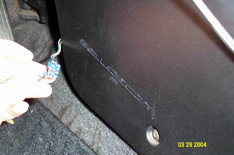
Step 2:
Make a Wire Jumper - Take a strand of copper wire and peel back shielding 1/4 inch on each side exposing the copper. Bend in a U shape. NOTE: You can also use a paper clip if you have to. 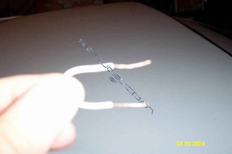
Step 3:
Insert Jumper into 2P Connector 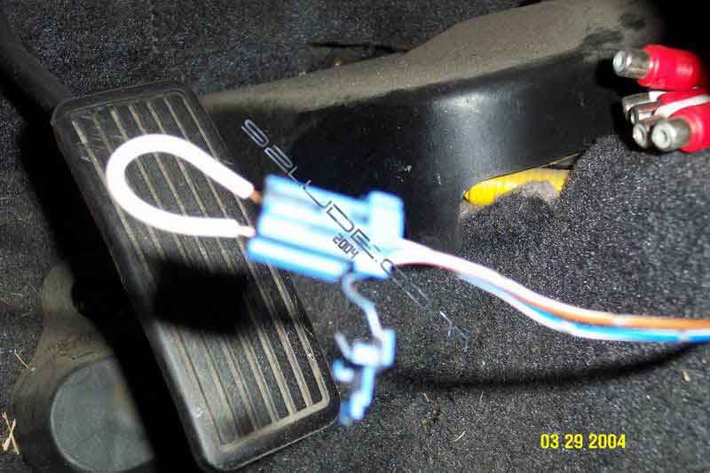
Step 4:
Turn the Ignition to the ON Position (Do Not Start)

Note the CODE: the Check Engine light indicates a failure code by the length and number of blinks. The Check Engine light can indicate simultaneous component problems by blinking separate codes, one after another. Problem codes 1 through 9 are indicated by individual short blinks. Problem codes 10 through 43 are indicated by a series of long and short blinks. The number of long blinks equals the first digit, the number of short blinks equals the second digit. 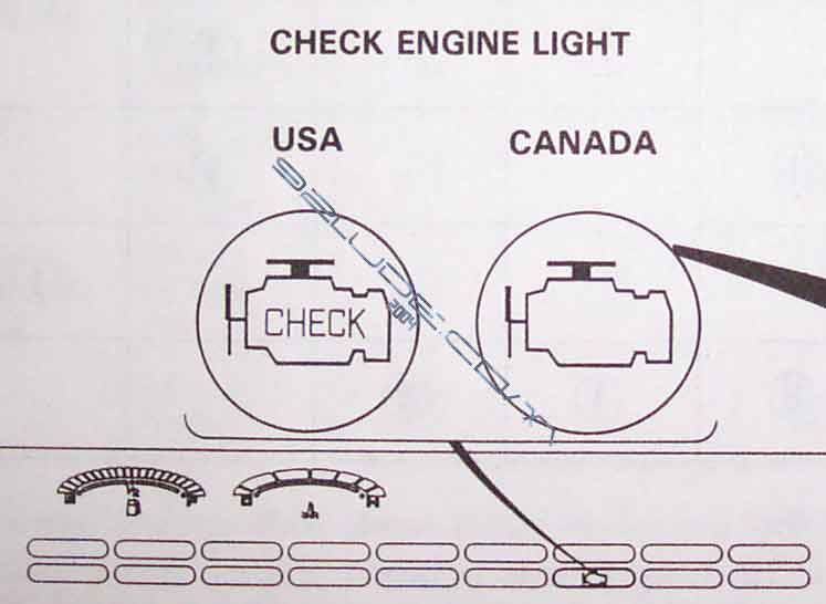
Step 5:
Do The ECU Reset Procedure.Step 6:
Set the Radio Preset Stations and Clock.These codes and page references pertain to the Helm Service Manual. You can obtain a Helm manual from our Downloads.